
Page 26 - Low Temperature Energy Systems with Applications of Renewable Energy
P. 26
Principles and operation of refrigeration and heat pump systems 15
Example 1 e Basic vapor-compression heat pump
With reference to Figs. 1.11 and 1.12, consider a heat pump with the following
specifications:
Cycle working fluid, refrigerant R152a
Heating capacity, 350 kWt
Compressor efficiency, 82%
R152a condenses at 100 C and evaporates at 20 C.
The NIST software Refprop will be used to determine the required properties of the
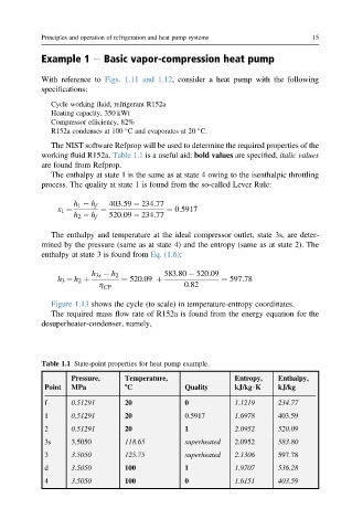
working fluid R152a. Table 1.1 is a useful aid: bold values are specified, italic values
are found from Refprop.
The enthalpy at state 1 is the same as at state 4 owing to the isenthalpic throttling
process. The quality at state 1 is found from the so-called Lever Rule:
h 1 h f 403:59 234:77
x 1 ¼ ¼ ¼ 0:5917
h 2 h f 520:09 234:77
The enthalpy and temperature at the ideal compressor outlet, state 3s, are deter-
mined by the pressure (same as at state 4) and the entropy (same as at state 2). The
enthalpy at state 3 is found from Eq. (1.6):
h 3s h 2 583.80 520.09
h 3 ¼ h 2 þ ¼ 520.09 þ ¼ 597:78
h CP 0.82
Figure 1.13 shows the cycle (to scale) in temperature-entropy coordinates.
The required mass flow rate of R152a is found from the energy equation for the
desuperheater-condenser, namely,
Table 1.1 State-point properties for heat pump example.
Pressure, Temperature, Entropy, Enthalpy,
Point MPa 8C Quality kJ/kg$K kJ/kg
f 0.51291 20 0 1.1219 234.77
1 0.51291 20 0.5917 1.6978 403.59
2 0.51291 20 1 2.0952 520.09
3s 3.5050 118.65 superheated 2.0952 583.80
3 3.5050 125.75 superheated 2.1306 597.78
d 3.5050 100 1 1.9707 536.28
4 3.5050 100 0 1.6151 403.59