
Page 25 - Low Temperature Energy Systems with Applications of Renewable Energy
P. 25
14 Low-Temperature Energy Systems with Applications of Renewable Energy
Temperature (A) 3s 3 Pressure P P (B)
T
4
EV
CN
d EV 4 d 3s 3
T EV P CN
f 1 2 f 1 2
Entropy Enthalpy
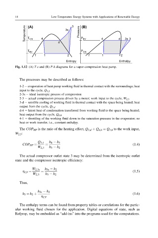
Fig. 1.12 (A) T-s and (B) P-h diagrams for a vapor-compression heat pump.
The processes may be described as follows:
1-2 e evaporation of heat pump working fluid in thermal contact with the surroundings; heat
input to the cycle, Q 1,2
2-3s e ideal isentropic process of compression
2-3 e actual compression process driven by a motor; work input to the cycle, W 2,3
3-d e sensible cooling of working fluid in thermal contact with the space being heated; heat
output from the cycle, Q 3,d
d-4 e latent heat of condensation transferred from working fluid to the space being heated;
heat output from the cycle, Q d,4
4-1 e throttling of the working fluid down to the saturation pressure in the evaporator; no
heat or work transfer, i.e., constant enthalpy.
The COP HP is the ratio of the heating effect, Q 3,d þ Q d,4 ¼ Q 3,4 to the work input,
W 2,3 :
Q 3;4 h 4 h 3
COP HP ¼ ¼ (1.4)
W 2;3 h 3 h 2
The actual compressor outlet state 3 may be determined from the isentropic outlet
state and the compressor isentropic efficiency:
W 2;3s h 3s h 2
h CP ¼ ¼ (1.5)
W 2;3 h 3 h 2
Thus,
h 3s h 2
h 3 ¼ h 2 þ (1.6)
h CP
The enthalpy terms can be found from property tables or correlations for the partic-
ular working fluid chosen for the application. Digital equations of state, such as
Refprop, may be embedded as “add-ins” into the programs used for the computations.