
Page 239 - Low Temperature Energy Systems with Applications of Renewable Energy
P. 239
226 Low-Temperature Energy Systems with Applications of Renewable Energy
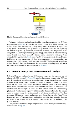
Fig. 6.2 Generalized flow diagram for a geothermal CHP system.
Whatever the heating application, a simplified general representation of a CHP sys-
tem is shown in Fig. 6.2. The geothermal source (1) may be a drilled well or a hot
spring; the geofluid is transmitted to the power plant (2) by a system of pipes (gath-
ering system); within the power plant various processes are carried out depending
on the type of plant, e.g., dry steam, flash steam or binary, and the geofluid is dis-
charged (3) still carrying useful energy and exergy. The fluid then enters the heating
application(s) where it supplies needed thermal energy for one or several applications,
some of which are shown in Fig. 6.1; see Fig. 5.1 for a more complete listing. The geo-
fluid is now in a low-energy state (4), close to the temperature of the surroundings and
possessing very little exergy. Finally, the spent geofluid (5) is disposed of, typically via
an injection well. The mass flow rates at the various state points in general will not be
the same, as we will see in the case studies in Section 6.3.
6.2 Generic CHP system: thermo-economic analysis
Before tackling case studies of actual CHP systems, we present first a general analysis
of a generic CHP system [1]. Figure 6.3 contains the essential elements of a CHP sys-
tem. The details of each element are not important for the thermodynamic systems
analysis shown below. State 3 leaving the turbine is a liquid, a vapor, or a liquid-
vapor mixture that normally enters a condenser and then passes to a water cooling
tower where the condensate is cooled for reuse in the condenser as the coolant. The
overflow from the cooling tower passes to a drain for reinjection. For noncondensing
plants, state 3, in this case a vapor, would be vented to the atmosphere, but this is rarely
done nowadays owing to environmental or efficiency considerations. The heat
exchanger HX transfers energy and exergy from the geothermal brine (state 7) to a
fresh water supply. Various end user applications may take place including domestic
hot water, space heating, or snow melting. Those details are not pertinent to this
generic analysis.
The processes involved in the plant operation are shown in temperature-entropy (T-
s) coordinates in Fig. 6.4.