
Page 240 - Low Temperature Energy Systems with Applications of Renewable Energy
P. 240
Geothermal energy in combined heat and power systems 227
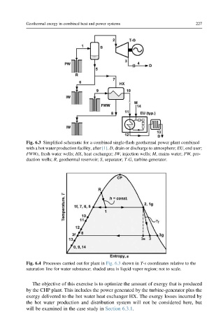
Fig. 6.3 Simplified schematic for a combined single-flash geothermal power plant combined
with a hot water production facility, after [1]. D, drain or discharge to atmosphere; EU, end user;
FWWs, fresh water wells; HX, heat exchanger; IW, injection wells; M, mains water; PW, pro-
duction wells; R, geothermal reservoir; S, separator; T-G, turbine-generator.
Fig. 6.4 Processes carried out for plant in Fig. 6.3 shown in T-s coordinates relative to the
saturation line for water substance; shaded area is liquid-vapor region; not to scale.
The objective of this exercise is to optimize the amount of exergy that is produced
by the CHP plant. This includes the power generated by the turbine-generator plus the
exergy delivered to the hot water heat exchanger HX. The exergy losses incurred by
the hot water production and distribution system will not be considered here, but
will be examined in the case study in Section 6.3.1.