
Page 248 - Low Temperature Energy Systems with Applications of Renewable Energy
P. 248
Geothermal energy in combined heat and power systems 235
plant, fluid at state 3 is a possible candidate for direct use. However, for a double-flash
plant the full flow rate at state 3 is best used to generate the low-pressure steam owing
to the relatively high value of the electricity over that of hot water. State 7 is the best
fluid available for direct use in that case, and the temperature is typically sufficiently
high for many applications. For example, a high-temperature resource found in New
Zealand, Kenya or Indonesia may be 320 C, and with a condensing temperature of
say 50 C, the roughly optimum division of temperature by the “Equal-temperature-
split rule” [4] leads to a separator at 230 C and a flasher at 140 C. From Fig. 6.1,
having geofluid at 140 C opens up many possibilities for direct heat usage. The
main drawback to such usage, from the point of view of the power plant, is the possi-
bility of loss of reinjection capacity. The lower the temperature of the separated geo-
fluid, the greater the likelihood of chemical scaling in the surface piping and in the
injection wells. Thus, for each resource the lower limit on geofluid temperature
must be determined to prevent such scaling. Even with such a limit, there are typically
many types of direct heat applications that can safely be entertained.
6.3.2 Organic Rankine cycles
Organic Rankine cycles (ORCs) tend to be deployed at low-to-moderate-temperature
resources. Applications are not limited to geothermal but may include any number of
waste heat recovery situations. Among all geothermal plants in the world, binary plants
rank first in total number of units in operation, and constitute about 35% of all plants
[4]. ORCs follow the basic Rankine cycle commonly used in fossil-fuel power plants,
but without many of the technical features used there for improving the thermal effi-
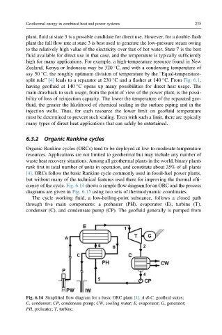
ciency of the cycle. Fig. 6.14 shows a simple flow diagram for an ORC and the process
diagrams are given in Fig. 6.15 using two sets of thermodynamic coordinates.
The cycle working fluid, a low-boiling-point substance, follows a closed path
through five main components: a preheater (PH), evaporator (E), turbine (T),
condenser (C), and condensate pump (CP). The geofluid generally is pumped from
Fig. 6.14 Simplified flow diagram for a basic ORC plant [4]. A-B-C, geofluid states;
C, condenser; CP, condensate pump; CW, cooling water; E, evaporator; G, generator;
PH, preheater; T, turbine.