
Page 142 - MATLAB an introduction with applications
P. 142
Control Systems ——— 127
(c) Time-Invariant System: A time-invariant system is a system described by a differential equation with
constant coefficients. Thus, the plant is time invariant if the parameters do not change as a function
of time. A linear time invariant system is described by linear differential equations with constant
coefficients. A single degree of freedom spring mass viscous damper system is an example of a time-
invariant system provided the characteristics of all the three components do not vary with time.
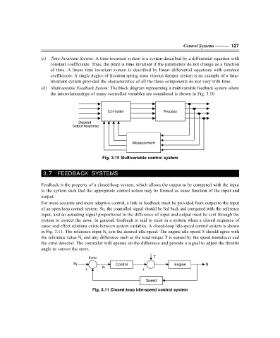
(d) Multivariable Feedback System: The block diagram representing a multivariable feedback system where
the interrelationships of many controlled variables are considered is shown in Fig. 3.10.
Controller Process
Desired
output response
Measurement
Fig. 3.10 Multivariable control system
3.7 FEEDBACK SYSTEMS
Feedback is the property of a closed-loop system, which allows the output to be compared with the input
to the system such that the appropriate control action may be formed as some function of the input and
output.
For more accurate and more adaptive control, a link or feedback must be provided from output to the input
of an open-loop control system. So, the controlled signal should be fed back and compared with the reference
input, and an actuating signal proportional to the difference of input and output must be sent through the
system to correct the error. In general, feedback is said to exist in a system when a closed sequence of
cause and effect relations exists between system variables. A closed-loop idle-speed control system is shown
in Fig. 3.11. The reference input N sets the desired idle-speed. The engine idle speed N should agree with
r
the reference value N and any difference such as the load-torque T is sensed by the speed-transducer and
r
the error detector. The controller will operate on the difference and provide a signal to adjust the throttle
angle to correct the error.
Error T
N r Control Engine N
N
+ +
Speed
Fig. 3.11 Closed-loop idle-speed control system
F:\Final Book\Sanjay\IIIrd Printout\Dt. 10-03-09