
Page 138 - MATLAB an introduction with applications
P. 138
Control Systems ——— 123
(d) Automatic traffic control (signal) system at roadway intersections
(e) Control system which automatically turns on a room lamp at dusk, and turns it off in daylight
(f ) Automatic hot water heater
(g) Environmental test-chamber temperature control system
(h) An automatic positioning system for a missile launcher
(i) An automatic speed control for a field-controlled DC motor
(j) The attitude control system of a typical space vehicle
(k) Automatic position-control system of a high speed automated train system
(l) Human heart using a pacemaker
(m) An elevator-position control system used in high-rise multilevel buildings.
3.4 CONTROL SYSTEM CONFIGURATIONS
There are two control system configurations: open-loop control system and closed-loop control system.
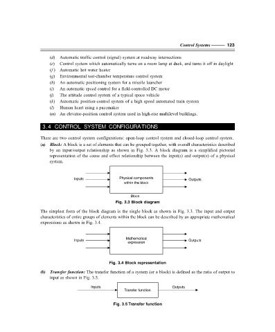
(a) Block: A block is a set of elements that can be grouped together, with overall characteristics described
by an input/output relationship as shown in Fig. 3.3. A block diagram is a simplified pictorial
representation of the cause and effect relationship between the input(s) and output(s) of a physical
system.
Inputs Physical components Outputs
within the block
Block
Fig. 3.3 Block diagram
The simplest form of the block diagram is the single block as shown in Fig. 3.3. The input and output
characteristics of entire groups of elements within the block can be described by an appropriate mathematical
expressions as shown in Fig. 3.4.
Mathematical
Inputs Outputs
expression
Fig. 3.4 Block representation
(b) Transfer function: The transfer function of a system (or a block) is defined as the ratio of output to
input as shown in Fig. 3.5.
Inputs Outputs
Transfer function
Fig. 3.5 Transfer function
F:\Final Book\Sanjay\IIIrd Printout\Dt. 10-03-09