
Page 139 - MATLAB an introduction with applications
P. 139
124 ——— MATLAB: An Introduction with Applications
Output
Transfer function =
Input
Transfer functions are generally used to represent a mathematical model of each block in the block diagram
representation. All the signals are transfer functions on the block diagrams. For instance, the time function
reference input is r(t), and its transfer function is R(s) where t is time and s is the Laplace transform variable
or complex frequency.
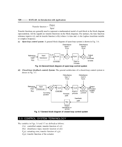
(c) Open-loop control system: A general block diagram of open-loop system is shown in Fig. 3.6.
Disturbance Disturbance
input 1 input 2
D (s) D (s)
1
2
E a (s) U(s)
Reference Input + Output
G c (s) G p (s)
Input transducer
+ Controlled
R(s) variable
Controller Plant or
Process
Fig. 3.6 General block diagram of open-loop control system
(d) Closed-loop (feedback control) System: The general architecture of a closed-loop control system is
shown in Fig. 3.7.
Disturbance Disturbance
input 1 input 2
D (s) D (s)
2
1
+ +
E a (s)
Reference Input + + + Output
G c (s) G p (s)
Input transducer Controlled
R(s) – Controller Plant or Summing variable
Summing Forward process junction C(s)
junction
path
Feedback
path
H(s)
Output
transducer or
sensor
Fig. 3.7 General block diagram of closed-loop control system
3.5 CONTROL SYSTEM TERMINOLOGY
The variables in Figs. 3.6 and 3.7 are defined as follows:
C(s) controlled output, transfer function of c(t)
D(s) disturbance input, transfer function of d(t)
E (s) actuating error, transfer function of e (t)
a
a
G (s) transfer function of the actuator
a
F:\Final Book\Sanjay\IIIrd Printout\Dt. 10-03-09