
Page 133 - MATLAB an introduction with applications
P. 133
118 ——— MATLAB: An Introduction with Applications
REFERENCES
Cogdell, J.R., Foundations of Electrical Circuits, Prentice-Hall, Englewood Cliffs, NJ, 1999.
Dorf, R.C., and Svoboda, J.A., Introduction to Electric Circuits, Wiley, New York, NY, 2006.
Fogiel, M., and Ogden, J.R., The Electric Circuits Problem Solver: A Complete Solution Guide to Any
Textbook, Research & Education Association, 1998.
th
Hayt, W.H., and Kemmerly, J.E., Engineering Circuit Analysis, 5 ed., McGraw-Hill, New York, NY, 1993.
rd
Johnson, D.E., Johnson, J.R. Hilburn, J.L., and Scott, P.D., Electric Circuit Analysis, 3 ed., Wiley, New
York, 1997.
Johnson, D.E., Basic Electric Circuit Analysis, 5 ed., Wiley, New York, 2006.
th
rd
Johnson, D.E., Hilburn, J.L., Johnson, J.R., and Scott, P.D., Electric Circuit Analysis, 3 ed., Prentice-
Hall, Englewood Cliffs, NJ, 1990.
th
Nahvi, M., Schaums Outline of Electrical Circuits, 4 ed., McGraw-Hill, New York, NY, 2002.
th
Nilsson, J.W., Electrical Circuits, 7 ed., Prentice-Hall, Englewood Cliffs, NJ, 2004.
Paul, C.R., Fundamentals of Electric Circuit Analysis, Wiley, New York, 2000.
Singh Guru, B., and Warrier, R., Electric Circuits—Analysis and Design, Oxford University Press, Oxford,
2005.
th
Smith, R.J., and Dorf, R.C., Circuits, Systems, and Devices, 5 ed., Wiley, New York, 1992.
Starr, A.T., Electrical Circuits and Wave Filters, Pitman Publishing, New York, 1938.
PROBLEMS
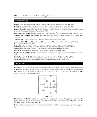
P2.1: Figure P2.1 shows an electrical circuit with resistors and voltage sources. Write a MATLAB program
to determine the current in each resistor, using the mesh current method based on Kirchhoff’s second voltage
law. Given V 1 = 37 V, V 2 = 19 V, V 3 = 25 V, R 1 = 16 Ω, R 2 = 19 Ω, R 3 = 11 Ω, R 4 = 10 Ω, R 5 = 6 Ω, R 6 = 15 Ω,
R 7 = 9 Ω, R 8 = 14 Ω, R 9 = 6 Ω and R 10 = 3 Ω.
R 1
V 1
R 2 R 3
R 9 R 10 R 4 V 2
R 5 R 6
R 7
V 3
R 8
Fig. P2.1
P2.2: Write a MATLAB program in a script file that computes the current through each resistor and the
power dissipated in each in a circuit that has resistors connected in parallel as shown in Fig. P2.2. Use the
script file for the circuit shown in Fig. P2.2.
Note that when several resistors are connected in a circuit in parallel, the current through each of them is given
by
F:\Final Book\Sanjay\IIIrd Printout\Dt. 10-03-09