
Page 201 - MEMS Mechanical Sensors
P. 201
190 Inertial Sensors
+
x-axis
Proof mass −
Sense
caps
V
step +
y-axis
−
Shield
+
z-axis
−
C ref
Figure 8.15 Pick-off circuit for three-axis accelerometer.
x-, y-, and z-axes, respectively. The improved performance is mainly attributed to
the lower resonant frequencies and the larger sense capacitance compared to the sin-
gle proof mass device.
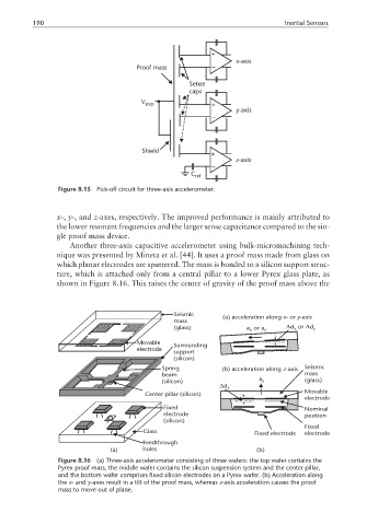
Another three-axis capacitive accelerometer using bulk-micromachining tech-
nique was presented by Mineta et al. [44]. It uses a proof mass made from glass on
which planar electrodes are sputtered. The mass is bonded to a silicon support struc-
ture, which is attached only from a central pillar to a lower Pyrex glass plate, as
shown in Figure 8.16. This raises the center of gravity of the proof mass above the
Seismic
(a) acceleration along x- or y- axis
mass
(glass) aor a y ∆dor ∆d y
x
x
Movable Surrounding
electrode
support
(silicon)
Spring (b) acceleration along -axis Seismic
z
beam mass
(silicon) a z (glass)
∆d z
Movable
Center pillar (silicon)
electrode
Fixed Nominal
electrode position
(silicon)
Fixed
Glass Fixed electrode electrode
Feedthrough
(a) holes (b)
Figure 8.16 (a) Three-axis accelerometer consisting of three wafers: the top wafer contains the
Pyrex proof mass, the middle wafer contains the silicon suspension system and the center pillar,
and the bottom wafer comprises fixed silicon electrodes on a Pyrex wafer. (b) Acceleration along
the x- and y-axes result in a tilt of the proof mass, whereas z-axis acceleration causes the proof
mass to move out of plane.