
Page 204 - MEMS Mechanical Sensors
P. 204
8.2 Micromachined Accelerometer 193
Fixed polysilicon
capacitor plates
Suspension
system Anchor
1.8V Ref.
Output
voltage
Demodulator
Buffer and lowpass Preamp
filter
3MΩ
Polysilicon proof Feedback voltage
mass and
moving
electrodes Square wave
oscillator
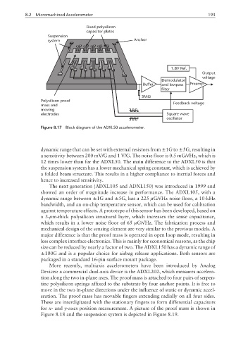
Figure 8.17 Block diagram of the ADXL50 accelerometer.
dynamic range that can be set with external resistors from ±1G to ±5G, resulting in
a sensitivity between 200 mV/G and 1 V/G. The noise floor is 0.5 mG/√Hz, which is
12 times lower than for the ADXL50. The main difference to the ADXL50 is that
the suspension system has a lower mechanical spring constant, which is achieved by
a folded beam structure. This results in a higher compliance to inertial forces and
hence to increased sensitivity.
The next generation (ADXL105 and ADXL150) was introduced in 1999 and
showed an order of magnitude increase in performance. The ADXL105, with a
dynamic range between ±1G and ±5G, has a 225 µG/√Hz noise floor, a 10-kHz
bandwidth, and an on-chip temperature sensor, which can be used for calibration
against temperature effects. A prototype of this sensor has been developed, based on
a3-µm-thick polysilicon structural layer, which increases the sense capacitance,
which results in a lower noise floor of 65 µG/√Hz. The fabrication process and
mechanical design of the sensing element are very similar to the previous models. A
major difference is that the proof mass is operated in open loop mode, resulting in
less complex interface electronics. This is mainly for economical reasons, as the chip
size can be reduced by nearly a factor of two. The ADXL150 has a dynamic range of
±100G and is a popular choice for airbag release applications. Both sensors are
packaged in a standard 16-pin surface mount package.
More recently, multiaxis accelerometers have been introduced by Analog
Devices: a commercial dual-axis device is the ADXL202, which measures accelera-
tion along the two in-plane axes. The proof mass is attached to four pairs of serpen-
tine polysilicon springs affixed to the substrate by four anchor points. It is free to
move in the two in-plane directions under the influence of static or dynamic accel-
eration. The proof mass has movable fingers extending radially on all four sides.
These are interdigitated with the stationary fingers to form differential capacitors
for x- and y-axes position measurement. A picture of the proof mass is shown in
Figure 8.18 and the suspension system is depicted in Figure 8.19.