
Page 209 - MEMS Mechanical Sensors
P. 209
198 Inertial Sensors
sensor since the scaling laws are unfavorable where friction is concerned, and hence,
there are no high-quality micromachined bearings. Consequently, nearly all MEMS
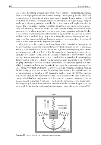
gyroscopes use a vibrating structure that couples energy from a primary, forced
oscillation mode into a secondary, sense oscillation mode. In Figure 8.22, a lumped
model of a simple gyroscope suitable for a micromachined implementation is
shown. The proof mass is excited to oscillate along the x-axis with a constant ampli-
tude and frequency. Rotation about the z-axis couples energy into an oscillation
along the y-axis whose amplitude is proportional to the rotational velocity. Similar
to closed loop micromachined accelerometers, it is possible to incorporate the sense
mode in a force-feedback loop. Any motion along the sense axis is measured and a
force is applied to counterbalance this sense motion. The magnitude of the required
force is then a measure of the angular rate signal.
One problem is the relatively small amplitude of the Coriolis force compared to
the driving force. Assuming a sinusoidal drive vibration given by x(t)= x sin(ω t),
0 d
where x is the amplitude of the oscillation and ω is the drive frequency, the Coriolis
0 d
acceleration is given by a =2v(t) ×Ω =2Ωx ω cos(ω t). Using typical values of x =
c 0 d d 0
2
1 µm, Ω = 1°/s, and ω =2π20 kHz, the Coriolis acceleration is only 4.4 mm/s .Ifthe
d
sensing element along the sense axis is considered as a second order mass-spring-
damper system with a Q = 1, the resulting displacement amplitude is only 0.0003
nm [51]. One way to increase the displacement is to fabricate sensing elements with
a high Q structure and then tune the drive frequency to the resonant frequency of the
sense mode. Very high Q structures, however, require vacuum packaging, making
the fabrication process much more demanding. Furthermore, the bandwidth of the
gyroscopes is proportional to ω /Q; hence, if a quality factor of 10,000 or more is
d
achieved in vacuum, the bandwidth of the sensor is reduced to only a few hertz.
Lastly, it is difficult to design structures for an exact resonance frequency, due to
manufacturing tolerances. A solution is to design the sense mode for a higher reso-
nant frequency than the drive mode and then decrease the resonant frequency of the
sense mode by tuning the mechanical spring constant using electrostatic forces [52].
Frame
mode
Sense Driven mode
Proof
mass
Input
rotation Ω
Figure 8.22 Lumped model of a vibratory rate gyroscope.