
Page 210 - MEMS Mechanical Sensors
P. 210
8.3 Micromachined Gyroscopes 199
An acceptable compromise between bandwidth and sensitivity is to tune the reso-
nant frequency of the sense mode close to the drive frequency (within 5% to 10%).
A second fundamental problem with vibratory rate micromachined gyroscopes
is due to so-called quadrature error. This type of error originates from manufactur-
ing tolerances manifesting themselves as a misalignment of the axis of the driven
oscillation from the nominal drive axis. As a result, a small proportion of the driven
motion will be along the sense axis. Even though the misalignment angle is very
small, due to the minute Coriolis acceleration, the resulting motion along the sense
axis may be much larger than the motion caused by the Coriolis acceleration.
8.3.2 Research Prototypes
8.3.2.1 Single-Axis Gyroscopes
Early micromachined gyroscopes were based on double-ended tuning forks. Two
tines, which are joined at a junction bar, are excited to resonate in antiphase along
one axis. Rotation causes the tines to resonate along the perpendicular axis.
Different actuation mechanisms can be used to excite the primary or driven oscilla-
tion mode. Examples of electromagnetic actuation are given in [53–56] and have the
advantage that large oscillation amplitudes are easily achievable. A severe disadvan-
tage, however, is that it requires a permanent magnet to be mounted in close prox-
imity to the sensing element, thereby making the fabrication process not completely
compatible with that of batch processing. Piezoelectric excitation has also been
reported, for example, by Voss et al. [57], who realized a double-ended tuning fork
structure with the oscillation direction perpendicular to the wafer surface using bulk
micromachining. The prevailing approach for prototype gyroscopes, however, is to
use electrostatic forces to excite the primary oscillation.
For detecting the secondary or sense oscillation, different position measurement
techniques have been used such as piezoresistive [56, 57], tunneling current [58],
optical [59], and capacitive, the latter being by far the predominant method.
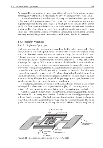
Greiff et al. [2], from the Charles Stark Draper Laboratories, presented a tuning
fork sensor that can be regarded as one of the first micromachined gyroscopes suit-
able for batch-processing. The bulk-micromachined sensing element is shown in
Figure 8.23. It is a two-gimbal structure supported by torsional flexures. The outer
gimbal structure is driven into oscillatory motion at 3 kHz out of the wafer plane by
Axis of sensitivity
Gyro element
Primary driven
oscillation
Electrodes
Secondary Gimbal structure
sense
oscillation
Figure 8.23 Gyroscope using a two-gimbal structure. (After: [2].)