
Page 211 - MEMS Mechanical Sensors
P. 211
200 Inertial Sensors
electrostatic forces. An automatic gain control (AGC) control loop ensures that the
oscillation amplitude is constant. In the presence of a rotation about the axis normal
to the sensing element plane, energy is transferred to the inner gimbal structure,
which starts vibrating at the same frequency at an amplitude proportional to the
angular spin rate. Maximum sensitivity is achieved when the drive frequency of the
outer structure is equal to the resonant frequency of the inner gimbal. The sensing
element could be operated in a force-balance mode. Electrostatic forces generated by
voltages on the feedback electrodes counterbalance the movement of the inner gim-
bal. The fixed electrodes above the inner and outer gimbal structure were fabricated
by an EDP wet-etch that removes sacrificial silicon dioxide. The lower electrodes
underneath the structure were implemented as p-type buried electrodes and are elec-
trically isolated by a reverse biased p-n junction from the substrate. The gap between
the fixed electrodes and the movable on the resonators is between 8 and 10 µm. To
increase the mass of the inner resonator, an inertial mass made from gold, of 25-µm
height, was electroformed.
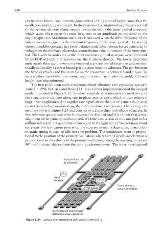
The first polysilicon surface-micromachined vibratory rate gyroscope was pre-
sented in 1996 by Clark and Howe [51]. It is a direct implementation of the lumped
model presented in Figure 8.22. Standard comb drive actuators were used to excite
the structure to oscillate along one in-plane axis (x-axis), which allows relatively
large drive amplitudes. Any angular rate signal about the out-of-plane axis (z-axis)
excites a secondary motion along the other in-plane axis (y-axis). The sensing ele-
ment is shown in Figure 8.24 and consists of a 2-µm-thick polysilicon structure. In
this reference quadrature error is discussed in detailed and it is shown that a mis-
alignment of the primary oscillation axis with the ideal x-axis of only one part in 3.6
million will result in a quadrature error equal to the signal of a 1°/sec rotation about
the z-axis. No fabrication process can be accurate to such a degree, and hence, elec-
trostatic tuning is used to alleviate this problem. The quadrature error is propor-
tional to the position of the primary oscillation, whereas the Coriolis acceleration is
proportional to the velocity of the primary oscillation; hence, the resulting forces are
90° out of phase (this explains the term quadrature error). The inner interdigitated
Structural anchor
to substrate
Input
Rotation Sense
Mode
Comb drives to
Driven Mode sustain oscillation
Interdigitated comb finger
deflection sense capacitors
Figure 8.24 Surface-micromachined gyroscope. (After: [51].)