
Page 212 - MEMS Mechanical Sensors
P. 212
8.3 Micromachined Gyroscopes 201
electrodes of the mechanical structure are used to exert an electrostatic force, which
is proportional to the position of the primary oscillation. Applying a biasing volt-
age, together with a small differential voltage, results in an electrostatic force that
allows counterbalancing of the unwanted motion of the proof mass of the primary
oscillation due to quadrature error. The paper also discusses the required interface
and control electronics for sustaining a constant amplitude and primary frequency
oscillation. For the latter, a phase-locked loop is chosen; for the former an
automatic gain control circuit is used. Furthermore, it is possible to tune the reso-
nant frequencies of the primary and secondary oscillation modes by applying
electrostatic negative springs. As a good compromise between bandwidth and sensi-
tivity, a mismatch of about 5% to 10% is suggested.
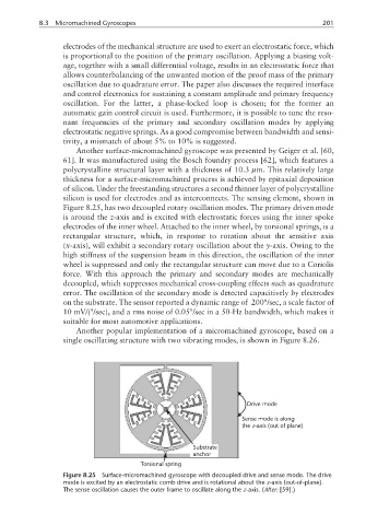
Another surface-micromachined gyroscope was presented by Geiger et al. [60,
61]. It was manufactured using the Bosch foundry process [62], which features a
polycrystalline structural layer with a thickness of 10.3 µm. This relatively large
thickness for a surface-micromachined process is achieved by epitaxial deposition
of silicon. Under the freestanding structures a second thinner layer of polycrystalline
silicon is used for electrodes and as interconnects. The sensing element, shown in
Figure 8.25, has two decoupled rotary oscillation modes. The primary driven mode
is around the z-axis and is excited with electrostatic forces using the inner spoke
electrodes of the inner wheel. Attached to the inner wheel, by torsional springs, is a
rectangular structure, which, in response to rotation about the sensitive axis
(x-axis), will exhibit a secondary rotary oscillation about the y-axis. Owing to the
high stiffness of the suspension beam in this direction, the oscillation of the inner
wheel is suppressed and only the rectangular structure can move due to a Coriolis
force. With this approach the primary and secondary modes are mechanically
decoupled, which suppresses mechanical cross-coupling effects such as quadrature
error. The oscillation of the secondary mode is detected capacitively by electrodes
on the substrate. The sensor reported a dynamic range of 200°/sec, a scale factor of
10 mV/(°/sec), and a rms noise of 0.05°/sec in a 50-Hz bandwidth, which makes it
suitable for most automotive applications.
Another popular implementation of a micromachined gyroscope, based on a
single oscillating structure with two vibrating modes, is shown in Figure 8.26.
Drive mode
Sense mode is along
z
the -axis (out of plane)
Substrate
anchor
Torsional spring
Figure 8.25 Surface-micromachined gyroscope with decoupled drive and sense mode. The drive
mode is excited by an electrostatic comb drive and is rotational about the z-axis (out-of-plane).
The sense oscillation causes the outer frame to oscillate along the z-axis. (After: [59].)