
Page 214 - MEMS Mechanical Sensors
P. 214
8.3 Micromachined Gyroscopes 203
results were reported for a structure 80 µm tall, operated at a low pressure (1
mTorr), which resulted in a quality factor for the oscillation of 1,000 to 2,000. This
was lower than expected and was attributed to anchor losses and voids inside the
polysilicon beams. Improved designs were expected to have a quality factor of up to
20,000. Similar to other micromachined gyroscopes, the resonant frequencies of
drive and sense mode were designed to be equal in order to amplify the sense mode
amplitude by the quality factor. Both resonant frequencies had a nominal value of
28.3 kHz. Any mismatch due to fabrication tolerances can be electrostatically tuned
by applying suitable voltages to the electrodes around the periphery of the ring. A
63-Hz mismatch was observed between the sense and drive modes, which required a
tuning voltage of only 0.9V. Other prototypes had a higher mismatch of up to 1 kHz
for which a tuning voltage of 6V was required to match sense and drive mode reso-
nant frequencies. The resolution of the device was measured to be less than 1°/sec
for a 1-Hz bandwidth; however, with some changes in the interface circuitry this
should be reduced to 0.01°/sec, which is then limited by the Brownian noise floor of
the structure.
8.3.2.2 Dual-Axis Gyroscopes
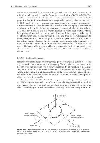
It is also possible to design micromachined gyroscopes that are capable of sensing
angular motion about two axes simultaneously. These devices are based on a rotor-
like structure that is driven into a rotary oscillation by electrostatic comb-drives.
Angular motion about the x-axis causes a Coriolis acceleration about the y-axis,
which, in turn, results in a tilting oscillation of the rotor. Similarly, any rotation of
the sensor about the x-axis causes the rotor to tilt about the x-axis. Conceptually,
this is shown in Figure 8.27.
An implementation of such a dual-axis gyroscope was reported by Junneau et
al. [67]. It was manufactured in a surface-micromachining process with a 2-m-thick
proof mass. The interface and control electronics were integrated on the same
chip. Underlying pie-shaped electrodes capacitively detect the tilting motion. To
z-axis drive
x-axis Coriolis
output oscillations y-axis Coriolis
output oscillations
Input rate Ω X Input rate Ω Y
Figure 8.27 A dual-axis gyroscope. A rotor is driven into rotational resonance; angular motion
about the x- and y-axes causes the rotor to tilt, which can be measured capacitively by electrodes
below it. (After: [66].)