
Page 200 - MEMS Mechanical Sensors
P. 200
8.2 Micromachined Accelerometer 189
alignment to the sense axes, as the sensing elements are defined by highly accurate
photolithographic methods. Three-axis sensors with piezoresistive, piezoelectric,
and capacitive position sensing mechanisms have been reported. Two approaches
are possible: a single proof mass that is compliant to move along two or even three
axes, or several proof masses integrated on one chip for the different sense axes.
Cross-axis sensitivity is a major issue with multiaxis accelerometers.
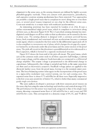
An interesting prototype has been reported by Lemkin et al. [42]. It uses a
surface-micromachined single proof mass, which is compliant to movement along
all three axes, as shown in Figure 8.14. The 2.3-µm-thick sensing element has inter-
digitated comb fingers on all four sides so that acceleration can be sensed in the two
in-plane axes. The sensing element is designed with a common centroid layout;
hence, both translational and rotational off-axis accelerations become a common
mode signal, which is rejected to the first order by the differential signal pick-off. It
is also compliant to movements out of plane, which changes the air-gap of a capaci-
tor formed by an electrode under the proof mass and the center section of the proof
mass. The pick-off circuit in this direction is quasidifferential as it is referenced to a
fixed capacitor, which is formed by a separate mechanical structure.
Figure 8.15 shows the front-end of the pick-off circuit. The proof mass, which
acts as the common node center node to all three capacitive half-bridges, is driven
with a step voltage, and the adjacent fixed electrodes are connected to a differential
charge amplifier. The output voltage is proportional to the differential change in
capacitance. Subsequently, this voltage is sampled and held, as the same capacitors
are then used as electrostatic actuators. Feedback voltage pulses are applied to the
electrode further away from the proof mass, forcing it to the nominal center posi-
tion. The force-balancing system relies again on the incorporation of the proof mass
in a sigma-delta modulator type control system, one for each sensing axes. The
reported noise floor is about 0.73 mG/√Hz for all three axes. Especially impressive
is the low cross-axis sensitivity of below 1%, which is better than many commercial
grade single-axis devices.
The same authors developed a prototype with three separate proof masses on
the same chip but using the same technology and interface and control strategy [43].
The performance for this sensor was improved, compared to that of the single-mass
sensor, showing a measured noise floor of 160 mG/√Hz for x- and y-axes and 990
mG/√Hz for z-axis. This corresponds to a dynamic range of 84, 81, and 70 dB for
Figure 8.14 Sensing element of a three-axis capacitive accelerometer.