
Page 198 - MEMS Mechanical Sensors
P. 198
8.2 Micromachined Accelerometer 187
PZT element
Top Supporting
electrode
beam
Inertial mass
(a) (b)
Figure 8.12 (a) Design of a piezoelectric accelerometer using thick-film printed PZT. (b) SEM
photograph of the sensing element.
controlled; hence, these sensors have to be used in closed loop operation. Electro-
static force-feedback is employed for the majority of research devices and this keeps
the separation distance approximately constant. The acceleration can then be
inferred from the voltage required to produce the necessary electrostatic force. A
typical sensing element is shown in Figure 8.13 [37]. The proof mass deflection elec-
trode is used to pull the proof mass, by the electrostatic force, into close proximity
so that a tunneling current begins to flow. The cantilever deflection electrode is used
for closed loop control to maintain the distance between the tip and the cantilever
constant.
Theoretically, this is the most sensitive detection mechanism. Several other
accelerometers based on this principle have been reported, but no commercial
device has been developed. One unresolved problem is the long-term drift of the
tunneling current as material from the tip is removed by the high electric fields.
8.2.2.5 Resonant Accelerometers
Resonant accelerometers consist of a proof mass that changes the strain in an
attached resonator, hence changing its resonant frequency, similar to tuning a guitar
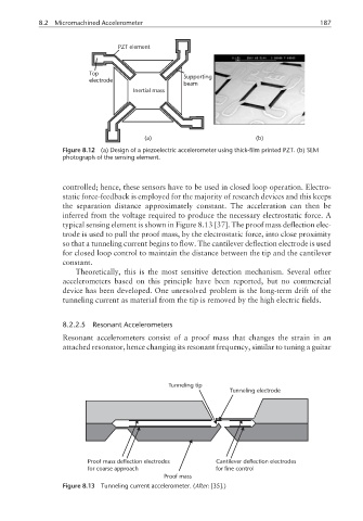
Tunneling tip
Tunneling electrode
Proof mass deflection electrodes Cantilever deflection electrodes
for coarse approach for fine control
Proof mass
Figure 8.13 Tunneling current accelerometer. (After: [35].)