
Page 194 - MEMS Mechanical Sensors
P. 194
8.2 Micromachined Accelerometer 183
Top electrode
Seismic mass
} } } C 1
Bottom
x
electrode
} } } C 2 1mm
5mm
Figure 8.8 A bulk-micromachined accelerometer with capacitive signal pick-off.
time-controlled etching in KOH with silicon dioxide as a mask. The same etch is
performed from the front and back sides of the wafer, resulting a highly symmetrical
design. The upper and lower wafers are anodically bonded to a glass wafer onto
which a thin layer of aluminum is deposited and patterned to form the electrodes.
Over-range stoppers restrict the movement of proof mass and prevent it from touch-
ing the electrodes, which could lead to an electrostatic latch-up. The performance of
the sensor depends on whether it is operated in open loop or closed loop mode, the
latter principally based on an analog force-feedback as described in Section 2.1.3.1.
For open loop operation the performance is well suited for general purpose and
automotive applications, whereas in closed loop operation sub-µg resolution was
reported to have made the device suitable for inertial navigation and guidance. The
resolution was below 1 µg/vHz in a bandwidth up to 100 Hz with a temperature
coefficient of offset and sensitivity of 30 µg/°C and 150 ppm/°C, respectively.
When capacitive sensors are operated in open loop mode, there exists one prob-
lem compared to piezoresistive devices in that the proof mass should move in paral-
lel to the electrodes, like a piston, rather than rotating around an axis, as with a
cantilever-type suspension system, which would introduce a nonlinearity for larger
deflections. Although several other cantilever capacitive accelerometer prototypes
Proof mass
Pyrex wafer
Suspension beams
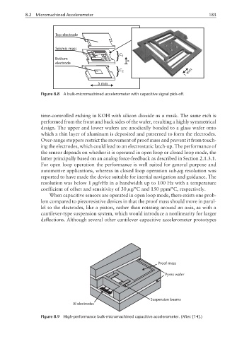
Al electrodes
Figure 8.9 High-performance bulk-micromachined capacitive accelerometer. (After: [14].)