
Page 195 - MEMS Mechanical Sensors
P. 195
184 Inertial Sensors
were presented [19, 20], more sophisticated suspension systems had to be designed
where the proof mass was connected to the substrate by several tethers and/or folded
beams. The design must be as symmetrical as possible in order to minimize cross-
axis sensitivity (i.e., acceleration along an axis other than the sense-axis should not
cause any change in capacitance) [21].
A range of high-performance devices has been reported, which were incorpo-
rated in a force-feedback sigma-delta modulator structure [7–10], as outlined in
Section 2.1.3.2. Henrion et al. [7] achieves a dynamic range of 120-dB resolution.
This, however, requires a high Q mechanical transfer function in order to achieve the
appropriate noise shaping for the sigma-delta modulator. This implies that the
sensing element has to be packaged in a vacuum. De Coulon et al. [8] used the sensing
element described in [18] and demonstrated that the digital control loop is suitable
to improve the performance. The bandwidth, in particular, has been improved
considerably from 3 Hz in the open loop case to about 100 Hz for closed loop
operation.
In the early to mid-1990s, the automotive market demanded cheap, reliable, and
medium-performance accelerometers. Initially, bulk-micromachined accelerometers
were used for these applications [14, 22], but this demand also led to a range of
surface-micromachined sensors to be developed with the sensing element and elec-
tronics integrated on the same chip. Of particular interested are the accelerometers
produced by Analog Devices [23–25] (described in more detail in Section 2.3). For
these sensors, the axis of sensitivity is typically in the wafer plane. The proof mass is
an order of magnitude smaller than that used in a bulk-micromachined device, and
hence, the sensitivity is less, which is partly compensated by integrating the pick-off
electronics on the same chip. The sensing element is typically formed by a 2-µm layer
of deposited polysilicon on top of a sacrificial silicon dioxide layer.
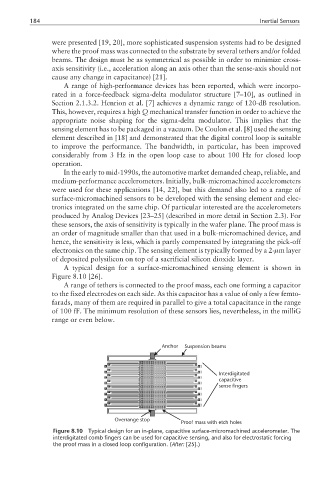
A typical design for a surface-micromachined sensing element is shown in
Figure 8.10 [26].
A range of tethers is connected to the proof mass, each one forming a capacitor
to the fixed electrodes on each side. As this capacitor has a value of only a few femto-
farads, many of them are required in parallel to give a total capacitance in the range
of 100 fF. The minimum resolution of these sensors lies, nevertheless, in the milliG
range or even below.
Anchor Suspension beams
Interdigitated
capacitive
sense fingers
Overrange stop
Proof mass with etch holes
Figure 8.10 Typical design for an in-plane, capacitive surface-micromachined accelerometer. The
interdigitated comb fingers can be used for capacitive sensing, and also for electrostatic forcing
the proof mass in a closed loop configuration. (After: [25].)