
Page 189 - MEMS Mechanical Sensors
P. 189
178 Inertial Sensors
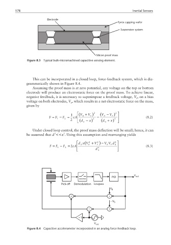
Electrode
Pyrex capping wafer
Suspension system
Silicon proof mass
Figure 8.3 Typical bulk-micromachined capacitive sensing element.
This can be incorporated in a closed loop, force-feedback system, which is dia-
grammatically shown in Figure 8.4.
Assuming the proof mass is at zero potential, any voltage on the top or bottom
electrode will produce an electrostatic force on the proof mass. To achieve linear,
negative feedback, it is necessary to superimpose a feedback voltage, V , on a bias
F
voltage on both electrodes, V , which results in a net electrostatic force on the mass,
B
given by
2 2
1 (V + V ) (V − V )
F = F − F = ε A B F − B F (8.2)
2
1
2 (d − x ) 2 (d + x ) 2
0
0
Under closed loop control, the proof mass deflection will be small; hence, it can
2
2
be assumed that d <<x . Using this assumption and rearranging yields
dx (V + V 2 )− V V d 2
2
F = F − F =2ε A 0 B F B F 0 (8.3)
1 2 4
d 0
V
PID out
Pick-off Demodulation Lowpass
V B
+ +
−V B
+ +
−1
V exc
Figure 8.4 Capacitive accelerometer incorporated in an analog force-feedback loop.