
Page 186 - MEMS Mechanical Sensors
P. 186
8.2 Micromachined Accelerometer 175
This chapter will introduce the fundamental principles and describe in more
detail some of the most important research prototype and commercial devices. Fur-
thermore, it will provide an outlook about the developments in this field to be
expected in the near future.
8.2 Micromachined Accelerometer
8.2.1 Principle of Operation
8.2.1.1 Mechanical Sensing Element
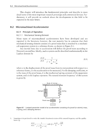
Many types of micromachined accelerometers have been developed and are
reported in the literature; however, the vast majority has in common that their
mechanical sensing element consists of a proof mass that is attached by a mechani-
cal suspension system to a reference frame, as shown in Figure 8.1.
Any inertial force due to acceleration will deflect the proof mass according to
Newton’s second law. Ideally, such a system can be described mathematically in the
Laplace domain by
()
xs 1
= (8.1)
()
as 2 b k
s + + s
m m
where x is the displacement of the proof mass from its rest position with respect to a
reference frame, a is the acceleration to be measured, b is the damping coefficient, m
is the mass of the proof mass, k is the mechanical spring constant of the suspension
1
system, and s is the Laplace operator. The natural resonant frequency of this system
is given by
Body of interest
Damper Spring
Proof mass
x
Figure 8.1 Lumped parameter model of an accelerometer consisting of a proof (or seismic) mass,
a spring, and a damping element.
1. Sometimes it is preferred to write the transfer function in terms of the natural frequency and the quality
factor Q:
()
xs 1 ω m mk
= with Q= n =
()
as 2 ω n 2 b b
s + s+ω n
Q