
Page 104 - MEMS and Microstructures in Aerospace Applications
P. 104
Osiander / MEMS and microstructures in Aerospace applications DK3181_c005 Final Proof page 92 25.8.2005 3:39pm
92 MEMS and Microstructures in Aerospace Applications
A radiation qualification procedure consists of a series of steps to ascertain
whether a part will operate properly in a radiation environment. The first step is to
define the environment by calculating its temporal and spatial compositions, that is,
fluxes, energies, and masses of the ions. Computer models, such as Space Radi-
1
ation , CREME96, and SPENVIS are available for predicting the flux of each
radiation component as a function of both location and time. The programs require
information such as launch date, mission duration, and orbital parameters, such as
perigee, apogee, and inclination.
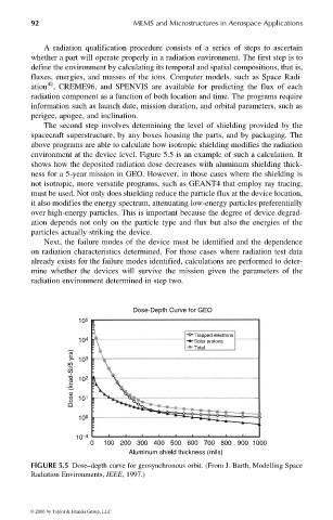
The second step involves determining the level of shielding provided by the
spacecraft superstructure, by any boxes housing the parts, and by packaging. The
above programs are able to calculate how isotropic shielding modifies the radiation
environment at the device level. Figure 5.5 is an example of such a calculation. It
shows how the deposited radiation dose decreases with aluminum shielding thick-
ness for a 5-year mission in GEO. However, in those cases where the shielding is
not isotropic, more versatile programs, such as GEANT4 that employ ray tracing,
must be used. Not only does shielding reduce the particle flux at the device location,
it also modifies the energy spectrum, attenuating low-energy particles preferentially
over high-energy particles. This is important because the degree of device degrad-
ation depends not only on the particle type and flux but also the energies of the
particles actually striking the device.
Next, the failure modes of the device must be identified and the dependence
on radiation characteristics determined. For those cases where radiation test data
already exists for the failure modes identified, calculations are performed to deter-
mine whether the devices will survive the mission given the parameters of the
radiation environment determined in step two.
Dose-Depth Curve for GEO
10 5
Trapped electrons
10 4 Solar protons
Total
Dose (krad-Si/5 yrs) 10 2 1
3
10
10
10 0
10 −4
0 100 200 300 400 500 600 700 800 900 1000
Aluminum shield thickness (mils)
FIGURE 5.5 Dose–depth curve for geosynchronous orbit. (From J. Barth, Modelling Space
Radiation Environments, IEEE, 1997.)
© 2006 by Taylor & Francis Group, LLC