
Page 106 - MEMS and Microstructures in Aerospace Applications
P. 106
Osiander / MEMS and microstructures in Aerospace applications DK3181_c005 Final Proof page 94 25.8.2005 3:39pm
94 MEMS and Microstructures in Aerospace Applications
off electrons bound to constituent atoms. Those electrons acquire sufficient energy
to break free from the atoms. As the liberated electrons (known as delta rays) travel
away from the generation site, they collide with other bound electrons, liberating
them as well. The result is an initially high density of electrons and holes that
together form a charge track coincident with the ion’s path. The initial diameter of
the track is less than a micron, but in a very short time — on the order of
picoseconds — the electrons diffuse away from the track and the initial high charge
density decreases rapidly.
The energy lost by an ion and absorbed in the material is measured in radiation
absorbed dose or rad(material). One rad(material) is defined as 100 ergs of energy
absorbed by 1 g of the material. Thus, for the case of silicon, the rad is given in terms
of how much energy is absorbed per gram of silicon, or rad(Si). Absorbed dose may
be calculated from Bethe’s formula, which gives the energy lost per unit length via
ionization by a particle passing through material, 10 as shown in the following
equation:
4 2
dE 4pe z
¼ NZB(m o , n, I) (5:1)
dx m o v 2
In the equation, n and z are the velocity and charge of the incoming particle, N and Z
are the number density and atomic number of the absorber atoms, m o is the electron
mass and e is the electron charge. I is the average ionization potential, which
is determined experimentally and depends on the type of material. For silicon
I ¼ 3.6 eV, whereas for GaAs I ¼ 4.8 eV. B(m o , n, I) is a slowly varying function
of n so that the energy lost by an ion traveling through material is greatest for highly
charged (large Z) incoming particles with low energy (small n).
A normalized form of this equation, independent of material density, is obtained
by dividing the differential energy loss by the material density (r) and is termed
linear energy transfer (LET), and is the metric used by most radiation test engineers
in the following equation:
1 dE
LET ¼ (5:2)
r dx
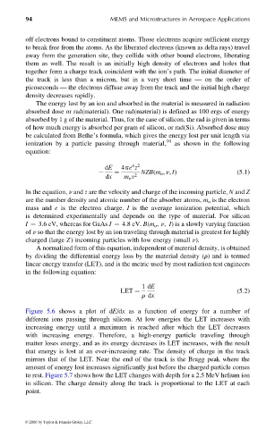
Figure 5.6 shows a plot of dE/dx as a function of energy for a number of
different ions passing through silicon. At low energies the LET increases with
increasing energy until a maximum is reached after which the LET decreases
with increasing energy. Therefore, a high-energy particle traveling through
matter loses energy, and as its energy decreases its LET increases, with the result
that energy is lost at an ever-increasing rate. The density of charge in the track
mirrors that of the LET. Near the end of the track is the Bragg peak where the
amount of energy lost increases significantly just before the charged particle comes
to rest. Figure 5.7 shows how the LET changes with depth for a 2.5 MeV helium ion
in silicon. The charge density along the track is proportional to the LET at each
point.
© 2006 by Taylor & Francis Group, LLC