
Page 110 - MEMS and Microstructures in Aerospace Applications
P. 110
Osiander / MEMS and microstructures in Aerospace applications DK3181_c005 Final Proof page 98 25.8.2005 3:39pm
98 MEMS and Microstructures in Aerospace Applications
electric field, which, in turn, changed the acceleration reading. Subsequent tests
of other MEMS devices, such as a RF switch, a micromotor and a digital mirror
device, also revealed radiation damage originating in insulating layers incorporated
in the mechanical structure. These results suggest a common theme for radiation
effects in MEMS that depend on sensing electric fields across insulators in the
mechanical portions, that is, charge deposited in insulating layers of MEMS modi-
fies existing electric fields in those layers, and the system responds by producing an
erroneous output.
The responses to radiation exposure of four different MEMS will be discussed
in detail. They include an accelerometer, a comb drive, a RF relay, and a digital
mirror device. In all cases the radiation damage is attributable to charge generated
in insulators that cause unwanted mechanical displacements. Inspection of these
four different MEMS confirms that there are no conceivable ways for SEE to occur
in the mechanical parts. Thus, no SEE testing was done.
5.3.1 ACCELEROMETER
ThefirstMEMSdevicesubjectedtoradiation testingwasacommercial accelerometer
(ADXL50) used primarily in the automotive industry for deploying air bags during a
collision. 13 Because of their small size, light weight, and low power consumption,
MEMS accelerometers also have applications in space, such as in small autonomous
spacecraft that are part of NASA’s New Millennium Program (NMP).
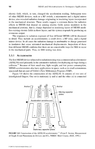
Figure 5.8 shows the construction of the ADXL50. It consists of two sets of
interdigitated fingers. One set is stationary (y and z) and the other (x) is connected
y y
Anchor z z Anchor
x x x
Moving capacitor
plates
Acceleration sensitive axis
x x x
z z
y y
Anchor Anchor
Stationary capacitor plates
FIGURE 5.8 Construction of the ADXL50 accelerometer. 13 (From F. Sexton, Measurement
of Single Event Phenomena in Devices and ICs, NSREC Short Course, IEEE, 1992.)
© 2006 by Taylor & Francis Group, LLC