
Page 113 - MEMS and Microstructures in Aerospace Applications
P. 113
Osiander / MEMS and microstructures in Aerospace applications DK3181_c005 Final Proof page 101 25.8.2005 3:39pm
Space Radiation Effects and Microelectromechanical Systems 101
electric fields between the fingers. That could cause one set of fingers to move
relative to the other. The result is a change in the capacitance between the two sets
of interdigitated fingers that results in a change in the output voltage.
The proposed mechanism of charge generation and trapping in the insulators
causing a shift in V out was confirmed by testing another accelerometer (ADXL04)
that contained a conducting polycrystalline silicon layer on top of the insulators.
That layer was electrically connected to the moveable set of fingers. The conducting
layer effectively screens out any charge generated in the insulators, so that the
mechanical part of the device should exhibit no radiation-induced changes. Irradi-
ation of the device with protons confirmed that there was no change in V out .
Mathematical modeling also confirmed that charge trapping in the insulators
could cause an offset in V out . 14 Another investigation showed that very high doses
of radiation actually caused the device to lock up and stop operating, presumably by
bending the beams to such an extent that they made contact with the substrate. 15
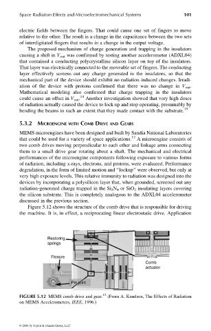
5.3.2 MICROENGINE WITH COMB DRIVE AND GEARS
MEMS microengines have been designed and built by Sandia National Laboratories
that could be used for a variety of space applications. 12 A microengine consists of
two comb drives moving perpendicular to each other and linkage arms connecting
them to a small drive gear rotating about a shaft. The mechanical and electrical
performances of the microengine components following exposure to various forms
of radiation, including x-rays, electrons, and protons, were evaluated. Performance
degradation, in the form of limited motion and ‘‘lockup’’ were observed, but only at
very high exposure levels. This relative immunity to radiation was designed into the
devices by incorporating a polysilicon layer that, when grounded, screened out any
radiation-generated charge trapped in the Si 3 N 4 or SiO 2 insulating layers covering
the silicon substrate. This is completely analogous to the ADXL04 accelerometer
discussed in the previous section.
Figure 5.12 shows the structure of the comb drive that is responsible for driving
the machine. It is, in effect, a reciprocating linear electrostatic drive. Application
Restoring
springs
Flexure
Comb
actuator
Pin joint
FIGURE 5.12 MEMS comb drive and gear. 12 (From A. Knudson, The Effects of Radiation
on MEMS Accelerometers, IEEE, 1996.)
© 2006 by Taylor & Francis Group, LLC