
Page 115 - MEMS and Microstructures in Aerospace Applications
P. 115
Osiander / MEMS and microstructures in Aerospace applications DK3181_c005 Final Proof page 103 25.8.2005 3:39pm
Space Radiation Effects and Microelectromechanical Systems 103
6.2 10 −12
6 10 −12
5.8 10 −12
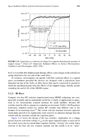
Radiation-Induced Trapped
C (Farads) 5.6 10 −12 Large Voltage Shift
Charge in Nitride Producing
5.4 10 −12
pre
6
5.2 10 −12 3*10 rads (SiO )
2
Die Grounded
5 10 −12
−40 −30 −20 −10 0 10 20 30 40
Bias (volts)
FIGURE 5.13 Capacitance as a function of voltage for a capacitor indicating the presence of
trapped charge. 12 (From L.P. Schanwald, Radiation Effects on Surface Micromachines
Combdrives and Microengines, IEEE, 1998.)
level it is possible that displacement damage effects cause fatigue in the polysilicon
spring attached to the one end of the comb drive.
In summary, microengines can operate with little radiation effects in a typical
space environment provided the devices are designed with a polysilicon layer
deposited on top of the Si 3 N 4 or SiO 2 layers that can be connected to ground to
shield the mechanical parts from the effects of the trapped charge, thereby greatly
extending the useful life of the MEMS engine.
5.3.3 RF RELAY
Compact, low-loss RF switches manufactured using MEMS technology are com-
mercially available and are potentially useful for a variety of applications in space,
such as for electronically scanned antennas for small satellites. Because RF
switches must be able to operate in a radiation environment, NASA’s Jet Propulsion
Laboratory radiation tested two similar RF switches that differed only in the
location of an insulating layer. 16 The switch with the insulator between capacitor
metal plates proved to be significantly more sensitive to radiation damage than the
switch with the insulator outside the capacitor plates.
Figure 5.14 shows the design of the two switches. Application of a voltage
greater than the activation voltage (V act ) to the upper capacitor plates at each end of
the switch, forces the two metal plates together, thereby ‘‘closing’’ the switch. Upon
removal of the bias, the two contacts separate and the switch is in its ‘‘open’’
© 2006 by Taylor & Francis Group, LLC