
Page 149 - MEMS and Microstructures in Aerospace Applications
P. 149
Osiander / MEMS and microstructures in Aerospace applications DK3181_c007 Final Proof page 138 1.9.2005 12:04pm
138 MEMS and Microstructures in Aerospace Applications
7.3.2 ADAPTIVE OPTICS APPLICATIONS
A similar application is the use of dense arrays of MEMS mirrors in adaptive optics
for space telescopes. In this case the requirements for the mirror motion are more
stringent: they need to be positioned continuously and not just toggled between two
positions. On terrestrial telescope applications, adaptive optics compensate for
atmospheric turbulence during observations. In principle, very faint objects can
be imaged during long exposures, provided there is a bright ‘‘reference beacon’’
nearby to allow the AO system to analyze the atmospheric effects. It is conceivable
that the same optics could be used in space-based applications to replace high-
precision heavy-weight mirrors with light-weight mirrors, which are themselves
adaptive or are corrected via adaptive optics. One principle for such a mirror array
has been developed at Boston University 43–48 and is commercially available
from Boston Micromachines. 49 The device offers a displacement of 2 mmwith
no hysteresis, and surface finishes of highly reflective gold or aluminum coating of
30 nm RMS. A similar device has been designed and fabricated by Vdovin et al., 50–
52
which also uses an electrostatic membrane mirror. This device has been demon-
strated at the Air Force Research Laboratory (AFRL). 53–56
Two other concepts, flexure-beam micromirror devices (FBMD) and axial-
rotation micromirror devices (ARMD), have been developed at the AFRL and
SNL. 57,58 These devices are fabricated in SNL’s four-level planarized polysilicon
process (SUMMiT V, see Chapter 3). Although square FBMDs are sufficient for
most applications, the same size array of ARMDs demonstrates significantly im-
proved performance since this device combines tilting and piston deflection. The
tilting of the ARMD mirror surface, in addition to its piston deflection, allows for a
closer adherence to the curvature of typical wavefront aberrations.
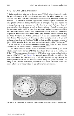
FIGURE 7.10 Photograph of assembled Fabry–Perot tunable filter. (Source: NASA GSFC.)
© 2006 by Taylor & Francis Group, LLC