
Page 361 - MEMS and Microstructures in Aerospace Applications
P. 361
Osiander / MEMS and microstructures in Aerospace applications DK3181_c016 Final Proof page 354 1.9.2005 12:56pm
354 MEMS and Microstructures in Aerospace Applications
Post release Gross leak test
device receipt MIL-STD-883 Method 1014
Condition C
Precap visual inspection
MIL-STD-883 Method 2010 Interim electricals at
Condition A or 25 C DC
(Hybrid Method 2017)
Burn-in test
Packaging and sealing MIL-STD-883 Method 1015
160 Hrs @ 125 C
Final electrical test
Stabilization bake
MIL-STD-883 Method 1008 + 25 C, +125 C, −55 C DC
Condition C
(Includes functional tests)
+ 25 C AC
Temperature cycling
MIL-STD-883 Method 1010
Condition C External visual
MIL-STD-883 Method 2009
Constant acceleration
MIL-STD-883 Method 2001
Condition E (Y1 Only) Move to next higher
integration step
Fine leak test
MIL-STD-883 Method 1014
Condition B
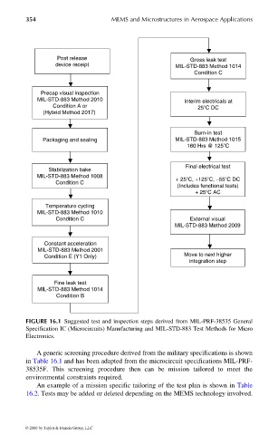
FIGURE 16.1 Suggested test and inspection steps derived from MIL-PRF-38535 General
Specification IC (Microcircuits) Manufacturing and MIL-STD-883 Test Methods for Micro
Electronics.
A generic screening procedure derived from the military specifications is shown
in Table 16.1 and has been adapted from the microcircuit specifications MIL-PRF-
38535F. This screening procedure then can be mission tailored to meet the
environmental constraints required.
An example of a mission specific tailoring of the test plan is shown in Table
16.2. Tests may be added or deleted depending on the MEMS technology involved.
© 2006 by Taylor & Francis Group, LLC