
Page 76 - Macromolecular Crystallography
P. 76
FIRST ANALYSIS OF MACROMOLECULAR CRYS TALS 65
(a) Cold gaseous (b)
nitrogen stream
(t = 180˚C)
Stream deflector
Goniometer head
assembled on X-ray
camera
(c) (d)
Loop-mounted
crystal Loop-mounted
crystal
(shock-cooled)
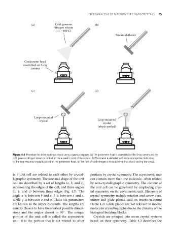
Figure 4.4 Procedure for shock-cooling a crystal using a gaseous cryogen. (a) The goniometer head is assembled on the X-ray camera and the
cold gaseous nitrogen stream is centred on the eucentric point of the camera. (b) The stream is deflected with some appropriate obstruction.
(c) The loop-mounted crystal is placed on the goniometer head. (d) The flow of cold nitrogen is re-established, thus shock-cooling the crystal.
in a unit cell are related to each other by crystal- portions by crystal symmetry. The asymmetric unit
lographic symmetry. The size and shape of the unit can contain more that one molecule, often related
cell are described by a set of lengths (a, b, and c), by non-crystallographic symmetry. The content of
representing the edges of the cell, and three angles the unit cell can be generated by employing crys-
(α, β, and γ) between these edges (Fig. 4.7). The tal symmetry on the asymmetric unit. Elements of
angle α is between b and c, β is between a and c, crystal symmetry include rotation and screw axes,
while γ is between a and b. These six parameters mirror and glide planes, and an inversion centre
are known as the lattice constants. The lengths are (Table 4.2). Glide planes are not relevant in macro-
usually chosen to have the shortest possible dimen- molecular crystallography due to the chirality of the
sions and the angles closest to 90 . The unique biological building blocks.
◦
portion of the unit cell is called the asymmetric Crystals are grouped into seven crystal systems
unit; it is the portion that is not related to other based on their symmetry. Table 4.3 describes the