
Page 95 - Macromolecular Crystallography
P. 95
84 MACROMOLECULAR CRYS TALLOGRAPHY
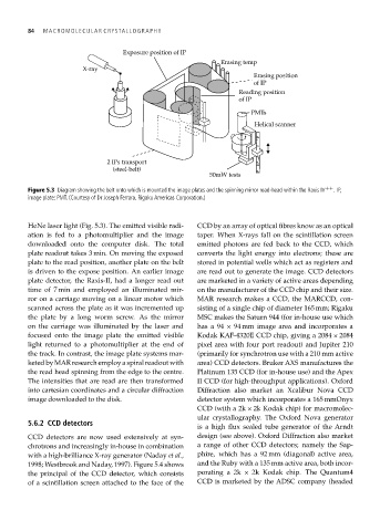
Exposure position of IP
Erasing temp
X-ray
Erasing position
of IP
Reading position
of IP
PMTs
Helical scanner
2 IPs transport
(steel-belt)
50mW tests
Figure 5.3 Diagram showing the belt onto which is mounted the image plates and the spinning mirror read-head within the Raxis IV ++ .IP,
image plate; PMT. (Courtesy of Dr Joseph Ferrara, Rigaku Americas Corporation.)
HeNe laser light (Fig. 5.3). The emitted visible radi- CCD by an array of optical fibres know as an optical
ation is fed to a photomultiplier and the image taper. When X-rays fall on the scintillation screen
downloaded onto the computer disk. The total emitted photons are fed back to the CCD, which
plate readout takes 3 min. On moving the exposed converts the light energy into electrons; these are
plate to the read position, another plate on the belt stored in potential wells which act as registers and
is driven to the expose position. An earlier image are read out to generate the image. CCD detectors
plate detector, the Raxis-II, had a longer read out are marketed in a variety of active areas depending
time of 7 min and employed an illuminated mir- on the manufacturer of the CCD chip and their size.
ror on a carriage moving on a linear motor which MAR research makes a CCD, the MARCCD, con-
scanned across the plate as it was incremented up sisting of a single chip of diameter 165 mm; Rigaku
the plate by a long worm screw. As the mirror MSC makes the Saturn 944 (for in-house use which
on the carriage was illuminated by the laser and hasa94 × 94 mm image area and incorporates a
focused onto the image plate the emitted visible Kodak KAF-4320E CCD chip, giving a 2084 × 2084
light returned to a photomultiplier at the end of pixel area with four port readout) and Jupiter 210
the track. In contrast, the image plate systems mar- (primarily for synchrotron use with a 210 mm active
keted by MAR research employ a spiral readout with area) CCD detectors. Bruker AXS manufactures the
the read head spinning from the edge to the centre. Platinum 135 CCD (for in-house use) and the Apex
The intensities that are read are then transformed II CCD (for high-throughput applications). Oxford
into cartesian coordinates and a circular diffraction Diffraction also market an Xcalibur Nova CCD
image downloaded to the disk. detector system which incorporates a 165 mmOnyx
CCD (with a 2k × 2k Kodak chip) for macromolec-
ular crystallography. The Oxford Nova generator
5.6.2 CCD detectors
is a high flux sealed tube generator of the Arndt
CCD detectors are now used extensively at syn- design (see above). Oxford Diffraction also market
chrotrons and increasingly in-house in combination a range of other CCD detectors; namely the Sap-
with a high-brilliance X-ray generator (Naday et al., phire, which has a 92 mm (diagonal) active area,
1998; Westbrook and Naday, 1997). Figure 5.4 shows and the Ruby with a 135 mm active area, both incor-
the principal of the CCD detector, which consists porating a 2k × 2k Kodak chip. The Quantum4
of a scintillation screen attached to the face of the CCD is marketed by the ADSC company (headed