
Page 104 - Make Your Own PCBs with EAGLE from Schematic Designs to Finished Boards
P. 104
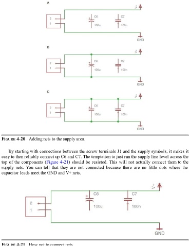
FIGURE 4-20   Adding nets to the supply area.


      By starting with connections between the screw terminals J1 and the supply symbols, it makes it
  easy to then reliably connect up C6 and C7. The temptation to just run the supply line level across the
  top of the components (Figure 4-21) should be resisted. This will not actually connect them to the
  supply  nets. You  can  tell  that  they  are  not  connected  because  there  are  no  little  dots  where  the
  capacitor leads meet the GND and V+ nets.


  FIGURE 4-21   How not to connect nets.