
Page 108 - Make Your Own PCBs with EAGLE from Schematic Designs to Finished Boards
P. 108
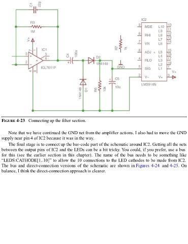
FIGURE 4-23   Connecting up the filter section.


      Note that we have continued the GND net from the amplifier actions. I also had to move the GND
  supply near pin 4 of IC2 because it was in the way.

      The final stage is to connect up the bar-code part of the schematic around IC2. Getting all the nets
  between the output pins of IC2 and the LEDs can be a bit tricky. You could, if you prefer, use a bus
  for  this  (see  the  earlier  section  in  this  chapter).  The  name  of  the  bus  needs  to  be  something  like
  “LEDS:CATHODE[1..10]” to allow the 10 connections to the LED cathodes to be made from IC2.
  The bus and direct-connection versions of the schematic are shown in Figures 4-24  and 4-25. On

  balance, I think the direct-connection approach is clearer.