
Page 113 - Make Your Own PCBs with EAGLE from Schematic Designs to Finished Boards
P. 113
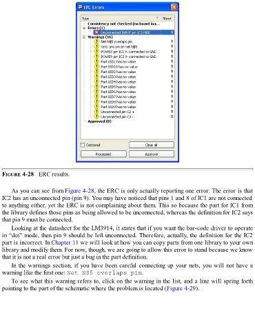
FIGURE 4-28   ERC results.


      As you can see from Figure 4-28, the ERC is only actually reporting one error. The error is that
  IC2 has an unconnected pin (pin 9). You may have noticed that pins 1 and 8 of IC1 are not connected

  to anything either, yet the ERC is not complaining about them. This so because the part for IC1 from
  the library defines those pins as being allowed to be unconnected, whereas the definition for IC2 says
  that pin 9 must be connected.

      Looking at the datasheet for the LM3914, it states that if you want the bar-code driver to operate
  in “dot” mode, then pin 9 should be left unconnected. Therefore, actually, the definition for the IC2
  part is incorrect. In Chapter 11 we will look at how you can copy parts from one library to your own
  library and modify them. For now, though, we are going to allow this error to stand because we know
  that it is not a real error but just a bug in the part definition.

      In the warnings section, if you have been careful connecting up your nets, you will not have a
  warning like the first one: Net N$5 overlaps pin.
      To see what this warning refers to, click on the warning in the list, and a line will spring forth

  pointing to the part of the schematic where the problem is located (Figure 4-29).