
Page 112 - Make Your Own PCBs with EAGLE from Schematic Designs to Finished Boards
P. 112
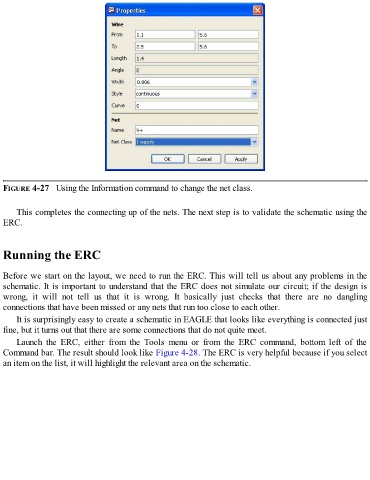
FIGURE 4-27   Using the Information command to change the net class.


      This completes the connecting up of the nets. The next step is to validate the schematic using the
  ERC.


  Running the ERC


  Before we start on the layout, we need to run the ERC. This will tell us about any problems in the
  schematic. It is important to understand that the ERC does not simulate our circuit; if the design is
  wrong,  it  will  not  tell  us  that  it  is  wrong.  It  basically  just  checks  that  there  are  no  dangling

  connections that have been missed or any nets that run too close to each other.
      It is surprisingly easy to create a schematic in EAGLE that looks like everything is connected just
  fine, but it turns out that there are some connections that do not quite meet.

      Launch  the  ERC,  either  from  the  Tools  menu  or  from  the  ERC  command,  bottom  left  of  the
  Command bar. The result should look like Figure 4-28. The ERC is very helpful because if you select
  an item on the list, it will highlight the relevant area on the schematic.