
Page 99 - Make Your Own PCBs with EAGLE from Schematic Designs to Finished Boards
P. 99
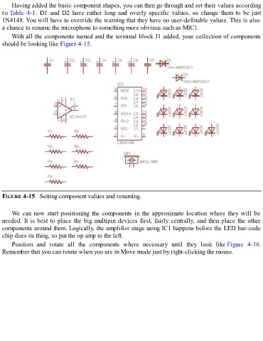
Having added the basic component shapes, you can then go through and set their values according
  to Table 4-1.  D1  and  D2  have  rather  long  and  overly  specific  values,  so  change  them  to  be  just
  1N4148. You will have to override the warning that they have no user-definable values. This is also
  a chance to rename the microphone to something more obvious such as MIC1.

      With all the components named and the terminal block J1 added, your collection of components
  should be looking like Figure 4-15.


  FIGURE 4-15   Setting component values and renaming.


      We  can  now  start  positioning  the  components  in  the  approximate  location  where  they  will  be
  needed. It is best to place the big multipin devices first, fairly centrally, and then place the other

  components around them. Logically, the amplifier stage using IC1 happens before the LED bar-code
  chip does its thing, so put the op amp to the left.
      Position  and  rotate  all  the  components  where  necessary  until  they  look  like Figure  4-16.
  Remember that you can rotate when you are in Move mode just by right-clicking the mouse.