
Page 94 - Make Your Own PCBs with EAGLE from Schematic Designs to Finished Boards
P. 94
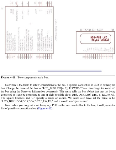
FIGURE 4-11   Two components and a bus.


      Now here’s the trick: to allow connections to the bus, a special convention is used in naming the

  bus. Change the name of the bus to “LCD_BUS1:DB[4..7], E,RW,RS.” You can change the name of
  the bus using the Name or Information commands. This name tells the bus object that any net being
  connected to it can be connected to one of eight possible slots: DB4, DB5, DB6, DB7, E, RW, or RS.
  The  square  brackets  and  “..”  specify  a  range  of  values.  We  could  also  have  set  the  name  to  be
  “LCD_BUS1:DB4,DB5,DB6,DB7,E,RW,RS,” and it would work just as well.

      Now, when you drag out a net from, say, PD7 on the microcontroller to the bus, it will present a
  list of possible connection slots (Figure 4-12).