
Page 100 - Make Your Own PCBs with EAGLE from Schematic Designs to Finished Boards
P. 100
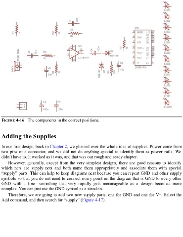
FIGURE 4-16   The components in the correct positions.


  Adding the Supplies


  In our first design, back in Chapter 2, we glossed over the whole idea of supplies. Power came from

  two pins of a connector, and we did not do anything special to identify them as power rails. We
  didn’t have to. It worked as it was, and that was our rough and ready chapter.
      However, generally, except from the very simplest designs, there are good reasons to identify

  which  nets  are  supply  nets  and  both  name  them  appropriately  and  associate  them  with  special
  “supply” parts. This can help to keep diagrams neat because you can repeat GND and other supply
  symbols so that you do not need to connect every point on the diagram that is GND to every other
  GND  with  a  line—something  that  very  rapidly  gets  unmanageable  as  a  design  becomes  more
  complex. You can just use the GND symbol as a stand-in.

      Therefore, we are going to add two new supply parts, one for GND and one for V+. Select the
  Add command, and then search for “supply” (Figure 4-17).