
Page 163 - Make Your Own PCBs with EAGLE from Schematic Designs to Finished Boards
P. 163
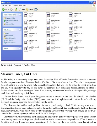
FIGURE 6-3   Generated Gerber files.


  Measure Twice, Cut Once


  At this point, it is extremely tempting to send the design files off to the fabrication service. However,
  the old carpentry maxim, “Measure Twice, Cut Once,” is very relevant here. There is nothing worse
  than submitting a job to be made only to suddenly realize that you had forgotten to check something
  and you would just have to pay for and await the return of a set of useless boards. Having said that, if
  the boards are just for a prototype, then a little surgery on incorrect boards is often possible, cutting a

  track here and soldering a link there.
      So now is the time to check your design once more to make sure that both the electric rule checker
  (ERC) and the design rule checker (DRC) have been run. Although these will catch a lot of problems,
  they will not guard against a design that is simply faulty.

      To illustrate this with a real problem, in my original design, I had D1 the wrong way around
  throughout the design, even in the schematic. I didn’t actually catch this problem until the boards came
  back. However, this was easily remedied by inserting the diode the “wrong” way around on the PCB.
  I then had to retrace my steps and redo all the PCB designs.

      Another problem is that it is often difficult to know if the parts you have picked out of the library
  have exactly the same package and pin dimensions as the components that you have. If this is the case,
  then it is well worth making a paper prototype. To do this, simply print out the board layout and try