
Page 162 - Make Your Own PCBs with EAGLE from Schematic Designs to Finished Boards
P. 162
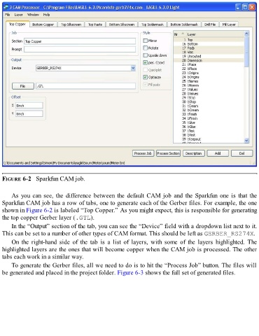
FIGURE 6-2   Sparkfun CAM job.


      As you can see, the difference between the default CAM job and the Sparkfun one is that the
  Sparkfun CAM job has a row of tabs, one to generate each of the Gerber files. For example, the one
  shown in Figure 6-2 is labeled “Top Copper.” As you might expect, this is responsible for generating
  the top copper Gerber layer (.GTL).

      In the “Output” section of the tab, you can see the “Device” field with a dropdown list next to it.
  This can be set to a number of other types of CAM format. This should be left as GERBER_RS274X.

      On  the  right-hand  side  of  the  tab  is  a  list  of  layers,  with  some  of  the  layers  highlighted.  The
  highlighted layers are the ones that will become copper when the CAM job is processed. The other
  tabs each work in a similar way.

      To generate the Gerber files, all we need to do is to hit the “Process Job” button. The files will
  be generated and placed in the project folder. Figure 6-3 shows the full set of generated files.