
Page 157 - Make Your Own PCBs with EAGLE from Schematic Designs to Finished Boards
P. 157
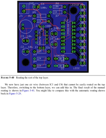
FIGURE 5-40   Routing the rest of the top layer.


      We now have just one air wire (between IC1 and C4) that cannot be easily routed on the top
  layer. Therefore, switching to the bottom layer, we can add this in. The final result of the manual
  routing is shown in Figure 5-41. You might like to compare this with the automatic routing shown
  back in Figure 5-28.