
Page 155 - Make Your Own PCBs with EAGLE from Schematic Designs to Finished Boards
P. 155
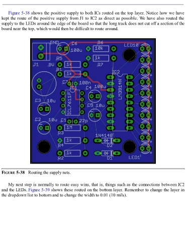
Figure 5-38 shows the positive supply to both ICs routed on the top layer. Notice how we have
  kept the route of the positive supply from J1 to IC2 as direct as possible. We have also routed the
  supply to the LEDs around the edge of the board so that the long track does not cut off a section of the
  board near the top, which would then be difficult to route around.


  FIGURE 5-38   Routing the supply nets.


      My next step is normally to route easy wins, that is, things such as the connections between IC2
  and the LEDs. Figure 5-39 shows these routed on the bottom layer. Remember to change the layer in
  the dropdown list to bottom and to change the width to 0.01 (10 mils).