
Page 156 - Make Your Own PCBs with EAGLE from Schematic Designs to Finished Boards
P. 156
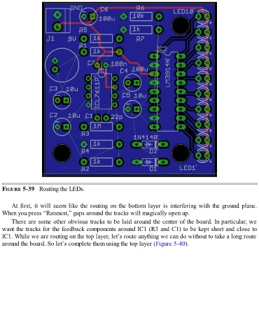
FIGURE 5-39   Routing the LEDs.


      At first, it will seem like the routing on the bottom layer is interfering with the ground plane.
  When you press “Ratsnest,” gaps around the tracks will magically open up.

      There are some other obvious tracks to be laid around the center of the board. In particular, we
  want the tracks for the feedback components around IC1 (R3 and C1) to be kept short and close to
  IC1. While we are routing on the top layer, let’s route anything we can do without to take a long route
  around the board. So let’s complete them using the top layer (Figure 5-40).