
Page 183 - Make Your Own PCBs with EAGLE from Schematic Designs to Finished Boards
P. 183
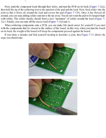
FIGURE 7-12   Soldering a resistor.

      First, push the component leads through their holes, and turn the PCB on its back (Figure 7-12a);
  then hold the tip of the soldering iron to the junction of the pad and the lead. Next, feed solder into the
  joint so that it flows all around the lead and covers the pad (Figure 7-12b). Once it has flowed all
  around, you can stop adding solder and move the tip away. You do not want the pad to be heaped high

  with solder. The solder ideally should form a nice “mountain” of solder around the lead (Figure 7-
  12c). Finally, you can snip off the excess lead (Figure 7-12d and e).
      When soldering components onto a PCB, you can make life much easier for yourself if you start

  with the components that lie closest to the surface of the board. In this way, when you turn the board
  on its back, the weight of the board will keep the components pressed against the board.
      If you make a mistake and find yourself needing to desolder a joint, then Figure 7-13 shows the
  steps you should take.