
Page 341 - 04. Subyek Engineering Materials - Manufacturing, Engineering and Technology SI 6th Edition - Serope Kalpakjian, Stephen Schmid (2009)
P. 341
Section 13.2
1 Backup rolls
hYdVaU|iC
Backing bearing
mechanism 7 ff; The Flat-rolling Process 32|
Screw or
[ _
i»- Housing
fiiiil
Chocks § § " Work rolls ff
W. _“_ VT W
Backup rolls
intermediate roli (D) Housing (C)
:::::: -.
(H)
,V
shape during rolling. just as a straight beam deflects under a
D""e" '°"
BGHVWIQ Shaft
Driven I'0||
Second
Smp
thicker at its center than at its edges (crown). The usual
Driven roll W ,, 5, Q if ' Efgimediate roll
@ ; <§= 5 °""°"
l ease W
~
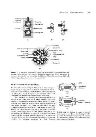
Because of the forces acting on them, rolls undergo changes in ,` Rolls
(d)
FIGURE I3.3
Schematic illustration of various roll arrangements: (a) four-high rolling mill
showing various features. The stiffness of the housing, the rolls, and the roll bearings are all
important in controlling and maintaining the thickness of the rolled strip; (b) two-high mill;
(c) three-high mill; and (d) cluster (or Sendzimir) mill.
" ' `
ttrtrtt ....
method of avoiding this problem is to grind the rolls in such a if , Strip thicker
l3.2.2 Geometric Considerations
at Centgr
transverse load, roll forces tend to bend the rolls elastically dur-
'iii
ing rolling (Fig. 13.4a). As expected, the higher the elastic mod-
(al
ulus of the roll material, the smaller the roll deflection.
As a result of roll bending, the rolled strip tends to be § `
way that their diameter at the center is slightly larger than at , ` . ifillérvéltllhickness
their edges (camber). Thus, when the roll bends, the strip N ~
,,,__,,,,
being rolled now has a constant thickness along its width (Fig. (b)
13.4b). For rolling sheet metals, the radius of the maximum
camber point is generally 0.25 mm greater than that at the
FIGURE l3.4 (a) Bending of straight cylindrical
edges of the roll. However, as expected, a particular camber is rolls caused by roll forces. (b) Bending of rolls
correct only for a certain load and strip width. To reduce the ground with camber, producing a strip with uniform
effects of deflection, the rolls also can be subjected to external thickness through the strip width. Deflections have
bending by applying moments at their bearings been exaggerated for clarity.