
Page 342 - 04. Subyek Engineering Materials - Manufacturing, Engineering and Technology SI 6th Edition - Serope Kalpakjian, Stephen Schmid (2009)
P. 342
322 Chapter 13 Metal-Rolling Processes and Equipment
Side view (a technique demonstrated simply by bending a wooden stick at its ends, a manip-
ulation that simulates camber).
Because of the heat generated by plastic deformation during rolling, rolls can
become slightly barrel shaped (thermal camber). Unless compensated for by some
means, this condition can produce strips that are thinner at the center than at the
edges. Consequently, the total (or final) camber can be controlled by adjusting the
location and the flow rate of the coolant along the length of the rolls during hot
rolling.
Roll forces also tend to flatten the rolls elastically, producing an effect much
like the flattening of automobile tires under load. Flattening of the rolls is undesir-
able, as it results, in effect, in a larger roll radius. This, in turn, means a larger con-
tact area for the same draft, and the roll force increases because of the now larger
(a)
contact area.
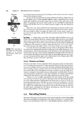
Top view Spreading. In rolling plates and sheets with high width-to-thickness ratios, the
width of the strip remains effectively constant during rolling. However, with smaller
ratios (such as a strip with a square cross section), its width increases significantly as
it passes through the rolls (an effect commonly observed in the rolling of dough with
a rolling pin). This increase in width is called spreading (Fig. 13.5). In the calcula-
(D) tion of the roll force, the width 1/U in Eq. (13.2) then is taken as an average width.
It can be shown that spreading increases with (a) decreasing width-to-thick-
FIGURE l3.5 Spreading in ness ratio of the entering strip (because of reduction in the width constraint), (b) in-
flat rolling. Note that similar
creasing friction, and (c) decreasing ratio of the roll radius to the strip thickness. The
spreading can be observed
last two effects are due to the increased longitudinal constraint of the material flow
when dough is rolled with a
in the roll gap. Spreading can be prevented also by using additional rolls (with verti-
rolling pin.
cal axes) in contact with the edges of the rolled product in the roll gap (edger mills),
thus providing a physical constraint to spreading.
l3.2.3 Vibration and Chatter
Vibration and chatter can have significant effects on product quality and the produc-
tivity of metalworking operations. Chatter, generally defined as self-excited vibration,
can occur in rolling as well as in extrusion, drawing, machining, and grinding opera-
tions. ln rolling, it leads to periodic variations in the thickness of the rolled sheet and
in its surface finish and, consequently, can lead to excessive scrap (see Table 40.3).
Chatter in rolling has been found to occur predominantly in tandem mills. Chatter is
very detrimental to productivity; it has been estimated, for example, that modern
rolling mills could operate at up to 50% higher speeds were it not for chatter.
Chatter is a very complex phenomenon (see also Section 25.4) and results
from interactions between the structural dynamics of the mill stand and the dynam-
ics of the rolling operation. Rolling speed and lubrication are found to be the two
most important parameters. Although not always practical to implement, it also has
been suggested that chatter can be reduced by increasing the distance between
the stands of the rolling mill, increasing the strip width, decreasing the reduction
per pass (draft), increasing the roll radius, increasing the strip-roll friction, and
incorporating dampers in the roll supports.
l3.3 Flat-rolling Practice
The initial rolling steps (breaking down) of the material typically is done by hot rolling
(above the recrystallization temperature of the metal; see Section 1.7). As described in
Section 10.2 and illustrated in Fig. 10.2, a cast structure typically is dendritic, and it