
Page 386 - 04. Subyek Engineering Materials - Manufacturing, Engineering and Technology SI 6th Edition - Serope Kalpakjian, Stephen Schmid (2009)
P. 386
Chapter 15 Metal Extrusion and Drawing Processes and Equipment
Mandrel Cgntainer Mandrel Die Container
Tube
Ram
Tube D'e
Ram
Spider
Billet
Billet 3p|der Mandrel
(H) (D)
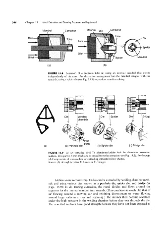
FIGURE l5.8 Extrusion of a seamless tube (a) using an internal mandrel that moves
independently of the ram. (An alternative arrangement has the mandrel integral with the
ram.) (b) using a spider die (see Fig. 15.9) to produce seamless tubing.
1»f .
~
llrrr
"i "i;i‘;‘! "" ' sw
¢= f" f 1€»ff f¢f~ '
2: .,,. Ji''mi "iil _
Egwelding sy €5;Spider r s
éichamber “ E§;Bridge
~ tv
lnlet \ 2
”
ports
(b) Porthole die (c) Spider die (d) Bridge die
FIGURE l5.9 (a) An extruded 6063-T6 aluminum-ladder lock for aluminum extension
ladders. This part is 8 mm thick and is sawed from the extrusion (see Fig. 152). lb) through
(d) Components of various dies for extruding intricate hollow shapes.
Source: (b) through (d) after K. Laue and H. Stenger.
Hollow cross sections (Fig. 15.9a) can be extruded by welding-chamber meth-
ods and using various dies known as a porthole die, spider die, and bridge die
(Figs. 15.9b to d). During extrusion, the metal divides and flows around the
supports for the internal mandrel into strands. (This condition is much like that of
air flowing around a moving car and rejoining downstream or water flowing
around large rocks in a river and rejoining.) The strands then become rewelded
under the high pressure in the Welding chamber before they exit through the die.
The rewelded surfaces have good strength because they have not been exposed to