
Page 382 - 04. Subyek Engineering Materials - Manufacturing, Engineering and Technology SI 6th Edition - Serope Kalpakjian, Stephen Schmid (2009)
P. 382
2 Chapter 15 Metal Extrusion and Drawing Processes and Equipment
In drawing, an operation that was developed between 1000 and 1500 A.D.,
the cross section of solid rod, wire, or tubing is reduced or changed in shape by
pulling it through a die. Drawn rods are used for shafts, spindles, and small pistons
and as the ravv material for fasteners (such as rivets, bolts, and screws). In addition
to round rods, various profiles can be drawn. The term drawing also is used to
refer to making cup-shaped parts by sheet-metal-forming operations, as described
in Section 16.7.
The distinction between the terms rod and Wire is somewhat arbitrary, with
rod taken to be larger in cross section than wire. In industry, wire generally is de-
fined as a rod that has been drawn through a die at least once, or its diameter is
small enough so that it can be coiled. Wire drawing involves smaller diameters than
rod drawing, with sizes down to 0.01 mm for magnet wire and even smaller for use
in very low current fuses.
15.2 The Extrusion Process
There are three basic types of extrusion. In the most common process (called direct
or forward extrusion), a billet is placed in a chamber (container) and forced through
a die opening by a hydraulically driven ram (pressing stem or punch), as shown in
Fig. 15.1. The die opening may be round, or it may have various shapes, depending
on the desired profile. The function of the dummy block shown in the figure is to
protect the tip of the pressing stem (punch), particularly in hot extrusion. Other
types of extrusion are indirect, hydrostatic, and impact extrusion.
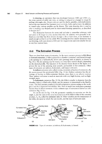
In indirect extrusion (also called reverse, inverted, or backward extrusion), the
die moves toward the unextruded billet (Fig. 15 .3a). Indirect extrusion has the ad-
vantage of having no billet-container friction, since there is no relative motion.
Thus, indirect extrusion is used on materials with very high friction, such as high-
strength steels.
__,- "(ii
In hydrostatic extrusion (Fig. 15 .3b), the billet is smaller in diameter than the
chamber (which is filled with a fluid), and the pressure is transmitted to the fluid by
a ram. The fluid pressure results in triaxial compressive stresses acting on the work-
piece and thus improved formability; also, there is much less workpiece-container
friction than in direct extrusion. A less common type of extrusion is lateral (or side)
extrusion (Fig. 15.3c).
As can be seen in Fig. 15.4, the geometric variables in extrusion are the die
angle, ot, and the ratio of the cross-sectional area of the billet to that of the extruded
product, AO/Af, called the extrusion ratio, R. Other variables are the temperature of
the billet, the speed at which the ram travels, and the type of lubricant used.
i
B'
Tool stem Dummyblock eas PUUCD ii '°'af@
S
Die ©
_,_
t
C
on ainer mer
,_,,,,
Container K Flwd Die holder
Extrusion
Backmg
Pressmg
¢ t
E’
Container
Extrusion Die Extrusion Die backer Container Die
(3) (D) (C)
FIGURE l5.3 Types of extrusion: (a) indirect; (b) hydrostatic; (c) lateral.