
Page 379 - 04. Subyek Engineering Materials - Manufacturing, Engineering and Technology SI 6th Edition - Serope Kalpakjian, Stephen Schmid (2009)
P. 379
Synthesis, Design, and Projects 359
QUANTITATIVE PROBLEMS
l4.24. Take two solid, cylindrical specimens of equal diam- D |4.29. Using Eq. (14.1), make a plot of the forging force,
eter, but different heights, and compress them (frictionless) F, as a function of the radius, r, of the workpiece. Assume
to the same percent reduction in height. Show that the final that the flow stress, Yf, of the material is constant. Remember
diameters will be the same. that the volume of the material remains constant during forg-
D l4.25. Calculate the forging force for a solid, cylindrical ing; thus, as h decreases, r increases.
workpiece made of 1020 steel that is 90 mm high and 125 l4.30. How would you go about calculating the punch
mm in diameter and is to be reduced in height by 30%. Let force required in a hubbing operation, assuming that the
the coefficient of friction be 0.15. material is mild steel and the projected area of the impression
|]l4.26. Using Eq. (14.2), estimate the forging force for is 320 mmf. Explain clearly. (Hint: See Section 2.6 on
the workpiece in Problem 14.25, assuming that it is a com- hardness.)
plex forging and that_ the projected area of the flash is 30% l4.3I. A mechanical press is powered by a 23-kW motor
greater than the projected area of the forged workpiece. and operates at 40 strokes per minute. It uses a flywheel, so
ll l4.27. To what thickness can a cylinder of 5052-O alu- that the crankshaft speed does not vary appreciably during the
minum that is 100 mm in diameter and 25 mm high be forged stroke. If the stroke is 150 mm, what is the maximum
in a press that can generate 450 kN? constant force that can be exerted over the entire stroke
length?
|] |4.28. In Example 14.1, calculate the forging force, as-
suming that the material is 1100-O aluminum and that the l4.3Z. Assume that you are an instructor covering the top-
coefficient of friction is 0.10. ics described in this chapter and you are giving a quiz on the
numerical aspects to test the understanding of the students.
Prepare two quantitative problems and supply the answers.
SYNTHESIS, DESIGN, AND PRO]ECTS
l4.33. Devise an experimental method whereby you can l4.36. In comparing forged parts with cast parts, we have
measure only the force required for forging the flash in im- noted that the same part may be made by either process.
pression-die forging. Comment on the pros and cons of each process, considering
14.34. Assume that you represent the forging industry and factors such as part size, shape complexity, design flexibility,
that you are facing a representative of the casting industry. mechanical properties developed, and performance in service.
What would you tell that person about the merits of forging D l4.37. From the data given in Table 14.3, obtain the ap-
processes? proximate value of the yield strength of the materials listed at
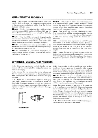
|4.35. Figure P14.35 shows a round impression-die forging hot-forging temperatures. Plot a bar chart showing the maxi-
mum diameter of a hot-forged part produced on a press with
made from a cylindrical blank, as illustrated on the left. As
described in this chapter, such parts are made in a sequence of a 60-ton capacity as a function of the material.
forging operations. Suggest a sequence of intermediate forg- l4.38. Review the sequence of operations in the production
ing steps to make the part on the right, and sketch the shape of the stepped pin shown in Fig. 14.13. If the conical-upsetting
of the dies needed. step is not performed, how would the final part be affected?
l4.39. Using a flat piece of wood, perform simple cogging
operations on pieces of clay and make observations regarding
the spread of the pieces as a function of the original cross
.....,
sections (for example, square or rectangular with different
thickness-to-width ratios).
l4.40. Discuss the possible environmental concerns regard-
ing the operations described in this chapter.
FIGURE P I 4.35