
Page 390 - 04. Subyek Engineering Materials - Manufacturing, Engineering and Technology SI 6th Edition - Serope Kalpakjian, Stephen Schmid (2009)
P. 390
370 Chapter 15 Metal Extrusion and Drawing Processes and Equipment
Investigating material flow during the defor- then polished and etched to display the grain flow,
mation of the slug helps avoid defects and leads to as shown in Fig. 15.14 (see also Fig. 14.11).
improvements in punch and die design. Furthermore,
the part usually is sectioned in the midplane and
FIGURE l5.I3 Production steps for a cold-extruded FIGURE l5.l4 A cross section of the metal part in
spark plug. Source: Courtesy of National Machinery Fig. 15 .13, showing the grain-flow pattern. Source:
Company. Courtesy of National Machinery Company.
l5.4.l Impact Extrusion
Impact extrusion is similar to indirect extrusion, and the process often is included in
the cold-extrusion category. The punch descends rapidly on the blank (slug), which
is extruded backwards (Fig. 15.15 ). Because of volume constancy, the thickness of
the tubular extruded section is a function of the clearance between the punch and
the die cavity.
Typical products made by this process are shown in Figs. 15.16a to c. Other
examples of products made by impact extrusion are collapsible tubes (similar to
those used for toothpaste), light fixtures, automotive parts, and small pressure ves-
sels. Most nonferrous metals can be impact extruded in vertical presses and at pro-
duction rates as high as two parts per second.
¢ '- . Slgléper
.
ii.'
2
=
s
Punch
PU"'Ch
J,
Stripper
;§_
.
plate
M Hank Clearance ‘
Die ,»ir Ei ""t““t"‘
(H) (D) (C)
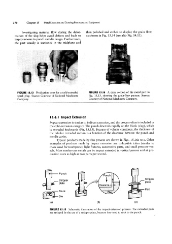
FIGURE l5.I5 Schematic illustration of the impact-extrusion process. The extruded parts
are stripped by the use of a stripper plate, because they tend to stick to the punch.